Amateur Extra E9B: Radiation patterns and modeling
These are the 11 official questions in group E9B of the 2024–2028 Amateur Extra question pool, with the correct answer marked and a plain-English explanation of why it's right. The real exam asks one question from this group.
- E9B01Question 1
What is the 3 dB beamwidth of the antenna radiation pattern shown in Figure E9-1?
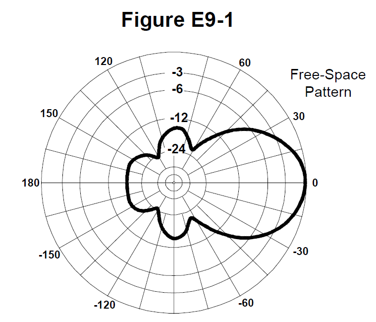
- A75 degrees
- B50 degrees Correct
- C25 degrees
- D30 degrees
Why: The pattern is 3 dB down 25° either side of the peak: 50° beamwidth.
- E9B02Question 2
What is the front-to-back ratio of the antenna radiation pattern shown in Figure E9-1?
- A36 dB
- B14 dB
- C24 dB
- D18 dB Correct
Why: The front-to-back ratio in E9-1 is 18 dB.
- E9B03Question 3
What is the front-to-side ratio of the antenna radiation pattern shown in Figure E9-1?
- A12 dB
- B24 dB
- C18 dB
- D14 dB Correct
Why: The front-to-side ratio in E9-1 is 14 dB.
- E9B04Question 4
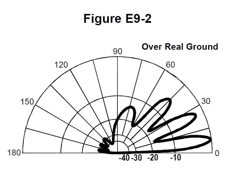
What is the front-to-back ratio of the radiation pattern shown in Figure E9-2?
- A15 dB
- B28 dB Correct
- C3 dB
- D38 dB
Why: The front-to-back ratio in E9-2 is 28 dB.
- E9B05Question 5
What type of antenna pattern is shown in Figure E9-2?
- AElevation Correct
- BAzimuth
- CNear field
- DPolarization
Why: E9-2 is an elevation pattern.
- E9B06Question 6
What is the elevation angle of peak response in the antenna radiation pattern shown in Figure E9-2?
- A45 degrees
- B75 degrees
- C7.5 degrees Correct
- D25 degrees
Why: E9-2 peaks at 7.5° elevation.
- E9B07Question 7
What is the difference in radiated power between a lossless antenna with gain and an isotropic radiator driven by the same power?
- AThe power radiated from the directional antenna is increased by the gain of the antenna
- BThe power radiated from the directional antenna is stronger by its front-to-back ratio
- CThey are the same Correct
- DThe power radiated from the isotropic radiator is 2.15 dB greater than that from the directional antenna
Why: Gain only concentrates power; the total radiated power is the same.
- E9B08Question 8
What is the far field of an antenna?
- AThe region of the ionosphere where radiated power is not refracted
- BThe region where radiated power dissipates over a specified time period
- CThe region where radiated field strengths are constant
- DThe region where the shape of the radiation pattern no longer varies with distance Correct
Why: The far field is where the pattern's shape no longer changes with distance.
- E9B09Question 9
What type of analysis is commonly used for modeling antennas?
- AGraphical analysis
- BMethod of Moments Correct
- CMutual impedance analysis
- DCalculus differentiation with respect to physical properties
Why: Antenna modeling commonly uses the Method of Moments.
- E9B10Question 10
What is the principle of a Method of Moments analysis?
- AA wire is modeled as a series of segments, each having a uniform value of current Correct
- BA wire is modeled as a single sine-wave current generator
- CA wire is modeled as a single sine-wave voltage source
- DA wire is modeled as a series of segments, each having a distinct value of voltage across it
Why: Method of Moments splits wires into segments, each with uniform current.
- E9B11Question 11
What is a disadvantage of decreasing the number of wire segments in an antenna model below 10 segments per half-wavelength?
- AGround conductivity will not be accurately modeled
- BThe resulting design will favor radiation of harmonic energy
- CThe computed feed point impedance may be incorrect Correct
- DThe antenna will become mechanically unstable
Why: Too few segments can give a wrong feed point impedance.