Amateur Extra E7B: Amplifier classes and circuits
These are the 12 official questions in group E7B of the 2024–2028 Amateur Extra question pool, with the correct answer marked and a plain-English explanation of why it's right. The real exam asks one question from this group.
- E7B01Question 1
For what portion of the signal cycle does each active element in a push-pull, Class AB amplifier conduct?
- AMore than 180 degrees but less than 360 degrees Correct
- BExactly 180 degrees
- CThe entire cycle
- DLess than 180 degrees
Why: Class AB devices conduct more than 180° but less than 360°.
- E7B02Question 2
What is a Class D amplifier?
- AAn amplifier that uses switching technology to achieve high efficiency Correct
- BA low power amplifier that uses a differential amplifier for improved linearity
- CAn amplifier that uses drift-mode FETs for high efficiency
- DAn amplifier biased to be relatively free from distortion
Why: A Class D amplifier uses switching for high efficiency.
- E7B03Question 3
What circuit is required at the output of an RF switching amplifier?
- AA filter to remove harmonic content Correct
- BA high-pass filter to compensate for low gain at low frequencies
- CA matched load resistor to prevent damage by switching transients
- DA temperature compensating load resistor to improve linearity
Why: A switching amplifier needs an output filter to remove harmonics.
- E7B04Question 4
What is the operating point of a Class A common emitter amplifier?
- AApproximately halfway between saturation and cutoff Correct
- BApproximately halfway between the emitter voltage and the base voltage
- CAt a point where the bias resistor equals the load resistor
- DAt a point where the load line intersects the zero bias current curve
Why: Class A sits about halfway between saturation and cutoff.
- E7B05Question 5
What can be done to prevent unwanted oscillations in an RF power amplifier?
- ATune the stage for minimum loading
- BTune both the input and output for maximum power
- CInstall parasitic suppressors and/or neutralize the stage Correct
- DUse a phase inverter in the output filter
Why: Parasitic suppressors and neutralization prevent unwanted oscillation.
- E7B06Question 6
What is a characteristic of a grounded-grid amplifier?
- AHigh power gain
- BLow input impedance Correct
- CHigh electrostatic damage protection
- DLow bandwidth
Why: A grounded-grid amplifier has low input impedance.
- E7B07Question 7
Which of the following is the likely result of using a Class C amplifier to amplify a single-sideband phone signal?
- AReduced intermodulation products
- BIncreased overall intelligibility
- CReduced third-order intermodulation
- DSignal distortion and excessive bandwidth Correct
Why: Class C isn't linear, so SSB gets distorted and too wide.
- E7B08Question 8
Why are switching amplifiers more efficient than linear amplifiers?
- ASwitching amplifiers operate at higher voltages
- BThe switching device is at saturation or cutoff most of the time Correct
- CLinear amplifiers have high gain resulting in higher harmonic content
- DSwitching amplifiers use push-pull circuits
Why: The switching device spends most of its time fully on or fully off, so it wastes little power.
- E7B09Question 9
What is characteristic of an emitter follower (or common collector) amplifier?
- ALow input impedance and phase inversion from input to output
- BDifferential inputs and single output
- CActs as an OR circuit if one input is grounded
- DInput and output signals in-phase Correct
Why: An emitter follower's input and output are in phase.
- E7B10Question 10
In Figure E7-1, what is the purpose of R1 and R2?
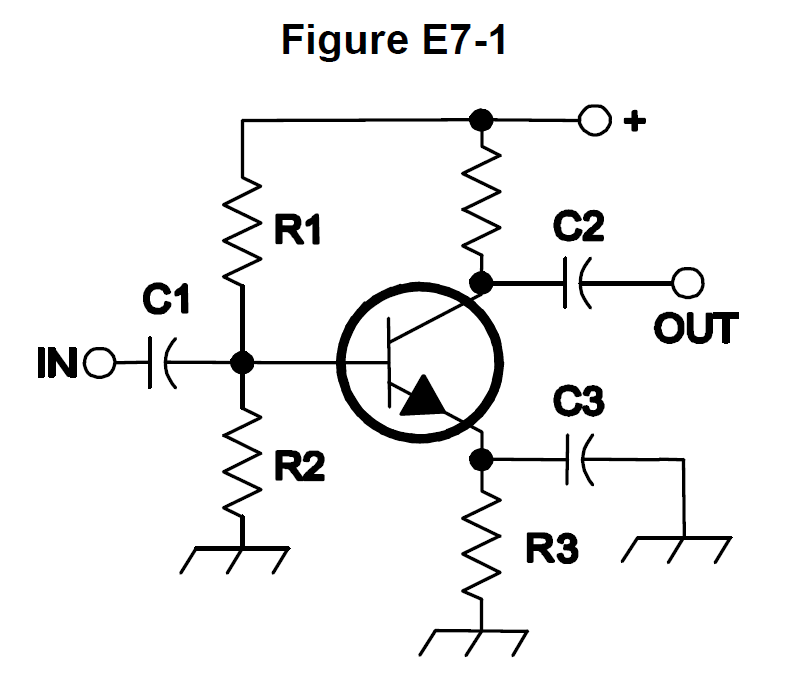
- ALoad resistors
- BVoltage divider bias Correct
- CSelf bias
- DFeedback
Why: R1 and R2 form a voltage divider that biases the base.
- E7B11Question 11
In Figure E7-1, what is the purpose of R3?
- AFixed bias
- BEmitter bypass
- COutput load resistor
- DSelf bias Correct
Why: R3 in the emitter provides self bias.
- E7B12Question 12
What type of amplifier circuit is shown in Figure E7-1?
- ACommon base
- BCommon collector
- CCommon emitter Correct
- DEmitter follower
Why: Figure E7-1 is a common emitter amplifier.